Monday, September 10. 2012
Pi For Dessert
Welcome to my Raspberry Pi!
Last week I ordered a new toy, one little Raspberry Pi and this blog will be dedicated to all the things I do with it.
As can be expected the first thing I did was to put a standard image on an SD card and bring it to life. It gladly obliged with beautiful 1920x1080 hdmi graphics. No surprises so far.
Next I decided that the ideal place for this blog to live is on the Rasberry Pi itself. So after installing and configuring LAMP we are off and running with this little blog being entirely served by the tiny little Raspberry Pi you see in this photo.
Enjoy my Pi, ... Robert Rath
Thursday, August 2. 2012
How To Modify Sea & Sea YS-50TTL For General Non-TTL Use
I had a Sea & Sea YS-50TTL strobe which was once use with the Motormarine II Camera. This strobe implemented TTL control through the camera metering in order to limit strobe power for correct exposure.
I have since replaced the original Motormarine cable with a Nikonos style connector using just the GND and X-SYNC pins in order to use with a housed camera. This was OK but I was limited to full power on every operation which lead to many frustrated photo dives. I had always intended to modify the strobe in order that the TTL switch could be used to reduce the strobe power to a fixed reduce power, for example 1 or 2 stops below full power.
I had put off making this modification for two reasons;
a) I could not find anywhere on the internet a full circuit diagram for the YS-50TTL strobe, and
b) reverse engineering the strobe myself would be a time consuming process.
In the end I chose step b) which involved recreating the circuit diagram by both tracing the board, its components and downloading component data for various devices. The only parts I was not able to identify the actual data for where the step up transformer, the trigger transformer and the flash tube. For the transformers I have made my best guess at their internal configuration.
The resulting circuit diagram presented here is my best effort which may include errors or omissions and I accept no responsibility for how this may be used. It serves my purpose of understanding how the strobe works including the TTL mechanism and enabled me to work out the modifications required to use the TTL switch for a fixed reduced power level.
There are two modifications identified on this circuit diagram. The first is the Fast Fire modification (http://www.devilgas.com/diving/ys50ttl/ys50ttl.asp) which I originally made a few years ago although it is not really necessary for a manual single fire strobe application. I have only included it because I have already made this change.
Fast Fire Modification
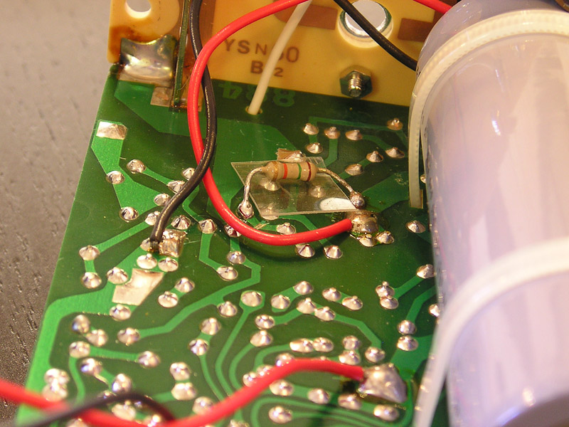
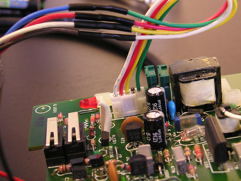
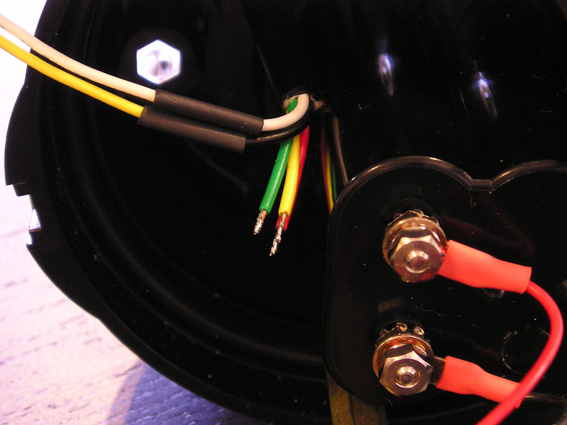
Here are my images for this modification as I approached it a little differently from the modification shown by DevilGas. Notice that rather than lift the diode off the PCB I have cut the PCB track instead to leave the diode in place on the PCB.
Manual Power Control Modification
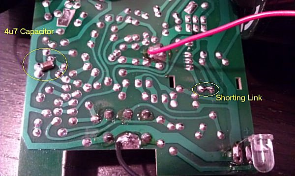
The second modification shown in the circuit diagram at the bottom right shows my solution to implement a reduced power setting via the TTL switch. The circuit shows a number of capacitor values which correspond to selectable power levels and and light outputs of -0.5, -1, -2 and -4 stops below full power. I have chosen 4u7 which creates -2 stops (or halves the guide number from 24 to 12).
Here are my images for this modification which you can appreciate are trivial.
Important Disclaimer
This information is provided purely to document my modifications and carries no implied warranty for either correctness of content or any consequence arising from its use by anyone else.
High power strobes used dangerous high voltage electronics and 300VDC or more may be charged and ready to bite (potentially fatally) even if the strobe is turned off.
Further more, modification such as these have the potential to destroy your precious digital camera if not implemented correctly and I accept no responsibility for any event arising.
... Robert Rath 3/8/2012
References For This Article
http://www.devilgas.com/diving/ys50ttl/ys50ttl.asp
http://www.camerasunderwater.co.uk/ttl-flash-interface
Files
Wednesday, November 24. 2010
Virtually COMM Unicating
Sometimes it is the simplest of things that really make my day. And what is really cool is where something simple is solved in a really complex way and made to appear simple! Almost like magic in fact!!
The Problem
I have a serial device next to me connected to the comm port of my Windows PC. Let's make it connected through a serial-usb adapter just to make things complicated. Next; I am developing an application on a remote virtual (vmware ) linux machine which needs to communicate with the small serial device next to me!
Problem 1. I have no direct access to the virtual machine in order to take my serial device and plug it into the virtual machine's host.
Problem 2. Even if I could have my little serial device plugged into my remote virtual machine's host I would no longer be able to interact with it during development work.
The simple solution would be to have my little serial device magically connected to my remote virtual machine and still be sitting next to me and my Windows PC.
Note my use of the word 'simple'; simple in description but not so in solution.
The Outcome
When a problem has been nagging to the point of being insufferable it is amazing how a little action, imagination and perseverance can produce magic.
With the help of two little tools; 'tcp2com
pm' and 'socat'; I am now able to enjoy the convenience of having my little serial device plugged into my Windows PC and being plugged into my remote virtual linux machine at the same time ... simply magic!
The Solution
I am not going to recount chapter and verse on how I made this magic happen. I don't want to make it easy for anyone else. So here is an incredibly terse, dot-point-list of actions I took:
On the Windows PC, install 'COM2TCPInstall_1_4_0.exe' or use 'tcp2com-1.0.0-bin.zip'
Configure tcp2com to export comm port and settings as required.
* For example on machine 10.0.0.10 export com4,57600,n,8,1,none to port 5555
On Linux
$ sudo apt-get install socat
$ sudo socat PTY,link=/dev/remotetty0,raw,echo=0,wait-slave tcp:10.0.0.10:5555
$ sudo kermit -l /dev/remotetty0
... enjoy
Virtually COMM Unicating
Sometimes it is the simplest of things that really make my day. And what is really cool is where something simple is solved in a really complex way and made to appear simple! Almost like magic in fact!!
The Problem
I have a serial device next to me connected to the comm port of my Windows PC. Let's make it connected through a serial-usb adapter just to make things complicated. Next; I am developing an application on a remote virtual (vmware ) linux machine which needs to communicate with the small serial device next to me!
Problem 1. I have no direct access to the virtual machine in order to take my serial device and plug it into the virtual machine's host.
Problem 2. Even if I could have my little serial device plugged into my remote virtual machine's host I would no longer be able to interact with it during development work.
The simple solution would be to have my little serial device magically connected to my remote virtual machine and still be sitting next to me and my Windows PC.
Note my use of the word 'simple'; simple in description but not so in solution.
The Outcome
When a problem has been nagging to the point of being insufferable it is amazing how a little action, imagination and perseverance can produce magic.
With the help of two little tools; 'tcp2com.exe' and 'socat'; I am now able to enjoy the convenience of having my little serial device plugged into my Windows PC and being plugged into my remote virtual linux machine at the same time ... simply magic!
The Solution
I am not going to recount chapter and verse on how I made this magic happen. I don't want to make it easy for anyone else. So here is an incredibly terse, dot-point-list of actions I took.
Setup
On Windows
Install 'COM2TCPInstall_1_4_0.exe' or use 'tcp2com-1.0.0-bin.zip'
Configure tcp2com to export comm port and settings as required.
Example, on machine 10.0.0.10 export com4,57600,n,8,1,none to port 5555
On Linux
$ sudo apt-get install socat
$ sudo socat PTY,link=/dev/remotetty0,raw,echo=0,wait-slave tcp:10.0.0.10:5555
Testing
On Windows
Open 'hypertrm' and connect to com4,57600,n,8,1,none
On Linux ( different console session )
$ sudo kermit -l /dev/remotetty0
C-Kermit->set flow none
C-Kermit->set carrier off
C-Kermit->set speed 57600
C-Kermit->connect
You should now be able to communicate between the two local terminals as if the machines were connected with a serial cable.
... enjoy
Monday, May 24. 2010
3-Way Windows-Linux-Windows Synchronisation With Unison
This script facilitates a 3-way synchronisation between two Windows shares and a hosted local directory. It requires no special software on the Windows machines, simply the sharing of respective directories. All the work of connecting to target machines and sychronising is done by the host using samba and unison.
It is assumed that samba, unison and a suitable mail configuration are installed on the linux host. The setup of these tools is beyond the scope of this documentation. Google is your friend if you need help.
In order to do a 3-way unison synchronisation we need first to sync between 1-2, then 2-3, then either 1-2 or 1-3 again to bring changes from 3 back into 1. So there are 3 independent sync's. For larger n-way syncs we need to add progressively more steps in order to ensure a full synchronisation. In this application where we are also hosting a known always available source we can assume will always be there. If we were simply facilitating an n-way sync without participating we would need to use a smarter algorithm to determine which end-points were available and sync between them accordingly.
As we check for a specific file before attempting a sync this file must be placed manually before any machine will be allowed to participate in sync operations. Removal of the check file will stop sync for the selected share which may be independent to each machine or common to all.
This script is suitable for running automatically as a cron job on the linux host server as often as needed.
In the event that a particular Windows machine was not found an error email will be generated.
The script allows for two names by which a Windows machine can be found. In many cases the second name will be the machine's IP address but use with care in DHCP environments. Having an alternative name or IP address is useful when a machine might sometimes be connected via LAN and other times by WiFi.
Here is the complete script which you will need to customise to suit your needs. In most cases you will only need to modify the variables as needed.
===========================================================
#!/bin/bash
# (c)2010 Robert Rath http://robertrath.com
# Common Variables
UNISON_OPTIONS="-perms 0 -batch -rsync -fastcheck true"
DESTINATION="/var/local/sync_directory_name_on_host_server"
DESTINATION_PATH=""
EMAIL="youremailaddress@youremaildomain"
EMAILMESSAGE="/tmp/emailmessage.txt"
NUMBER_OF_MACHINES="2"
# Source 1 Variables
SOURCE_MACHINE="NameOfWindowsMachine1"
ALT_MACHINE="IPAddressOfWindowsMachine1"
SOURCE_CREDENTIALS="/root/.smbpasswords/file_containing_machine1_windows_credentials"
MOUNT="/mnt/mount_directory_name_on_host_server"
SOURCE="NameOfWindowsMachine1SharedDirectory"
SOURCE_PATH="/PathFromRootOfWindowsMachine1SharedDirectory" # Leave blank,ie "", if using root of share, start with "/path" otherwise.
CHECK_FILE="initial_check_file_1" # This file must pre-exist/always-exist for sync to take place, use an initial backslash if not root of share.
# Source 2 Variables
SOURCE_MACHINE_2="NameOfWindowsMachine2"
ALT_MACHINE_2="IPAddressOfWindowsMachine2"
SOURCE_CREDENTIALS_2="/root/.smbpasswords/file_containing_machine2_windows_credentials"
MOUNT_2="/mnt/mount_directory_name_on_host_server_2"
SOURCE_2="NameOfWindowsMachine2SharedDirectory"
SOURCE_PATH_2="/PathFromRootOfWindowsMachine2SharedDirectory" # Leave blank,ie "", if using root of share, start with "/path" otherwise.
CHECK_FILE_2="initial_check_file_2" # This file must pre-exist/always-exist for sync to take place, use an initial backslash if not root of share.
# Sync the first machine with the server
# ======================================
if [ $((NUMBER_OF_MACHINES)) -ge 1 ]; then
echo sync-$DESTINATION$DESTINATION_PATH : Begin Synchronise $SOURCE Between $SOURCE_MACHINE and Server # Inform user of intention
/bin/mkdir -p "$DESTINATION$DESTINATION_PATH" # create the host sync directory
/bin/mkdir -p "$MOUNT" # create the mount point
rm -f $TMPLOG # remove an existing temp log file
# The remote machine may be at one of two host names so we need to check both in the prefered order
/bin/mount -t cifs -o credentials=$SOURCE_CREDENTIALS "//$SOURCE_MACHINE/$SOURCE" "$MOUNT" # mount machine share source to mount path
if [ ! -e "$MOUNT/$SOURCE_PATH$CHECK_FILE" ]; then # if mount was unsuccessful on 'first' then try 'alternative'
echo "Could not find primary target so attempting secondary target"
/bin/mount -t cifs -o credentials=$SOURCE_CREDENTIALS "//$ALT_MACHINE/$SOURCE" "$MOUNT" # mount alternate
fi
if [ -e "$MOUNT/$SOURCE_PATH$CHECK_FILE" ]; then # check if the mount was successful before doing sync
/usr/local/bin/unison-2.9.1 $UNISON_OPTIONS "$DESTINATION$DESTINATION_PATH" "$MOUNT$SOURCE_PATH" # use the unison program for synchronisation
if [ "$?" -eq "0" ]; then
SUBJECT="Succes: sync-$DESTINATION$DESTINATION_PATH - Synchronised sync-$SOURCE Between $SOURCE_MACHINE and Server using 'unison $UNISON_OPTIONS'" # success
elif [ "$?" -eq "1" ]; then
SUBJECT="Conflict: sync-$DESTINATION$DESTINATION_PATH - Conflicting sync-$SOURCE Between $SOURCE_MACHINE and Server using 'unison $UNISON_OPTIONS'" # sync conflict
else
SUBJECT="Error: sync-$DESTINATION$DESTINATION_PATH - Error sync-$SOURCE Between $SOURCE_MACHINE and Server using 'unison $UNISON_OPTIONS'" # sync error
fi
else
SUBJECT="Offline: sync-$DESTINATION$DESTINATION_PATH - Offline sync-$SOURCE to $SOURCE_MACHINE no sync attempt possible'" # offline error
fi
echo "$SUBJECT" # echo result to terminal
echo "$SUBJECT"> $EMAILMESSAGE
/usr/bin/mail -s "$SUBJECT" "$EMAIL" < $EMAILMESSAGE
/bin/umount "$MOUNT" # unmount mount path
fi
# Sync the second machine with the server
# ======================================
if [ $((NUMBER_OF_MACHINES)) -ge 2 ]; then
echo sync-$DESTINATION$DESTINATION_PATH : Begin Synchronise $SOURCE_2 Between $SOURCE_MACHINE_2 and Server # Inform user of intention
/bin/mkdir -p "$DESTINATION$DESTINATION_PATH" # create the host sync directory
/bin/mkdir -p "$MOUNT_2" # create the mount point
# The remote machine may be at one of two host names so we need to check both in the prefered order
/bin/mount -t cifs -o credentials=$SOURCE_CREDENTIALS_2 "//$SOURCE_MACHINE_2/$SOURCE_2" "$MOUNT_2" # mount machine share source to mount path
if [ ! -e "$MOUNT_2/$SOURCE_PATH_2$CHECK_FILE_2" ]; then # if mount was unsuccessful on 'first' then try 'alternative'
echo "Could not find primary target so attempting secondary target"
/bin/mount -t cifs -o credentials=$SOURCE_CREDENTIALS_2 "//$ALT_MACHINE_2/$SOURCE_2" "$MOUNT_2" # mount alternate
fi
if [ -e "$MOUNT_2/$SOURCE_PATH_2$CHECK_FILE_2" ]; then # check if the mount was successful before doing sync
/usr/local/bin/unison-2.9.1 $UNISON_OPTIONS "$DESTINATION$DESTINATION_PATH" "$MOUNT_2$SOURCE_PATH_2" # use the unison program for synchronisation
if [ "$?" -eq "0" ]; then
SUBJECT="Succes: sync-$DESTINATION$DESTINATION_PATH - Synchronised sync-$SOURCE_2 Between $SOURCE_MACHINE_2 and Server using 'unison $UNISON_OPTIONS'" # success
elif [ "$?" -eq "1" ]; then
SUBJECT="Conflict: sync-$DESTINATION$DESTINATION_PATH - Conflicting sync-$SOURCE_2 Between $SOURCE_MACHINE_2 and Server using 'unison $UNISON_OPTIONS'" # sync conflict
else
SUBJECT="Error: sync-$DESTINATION$DESTINATION_PATH - Error sync-$SOURCE_2 Between $SOURCE_MACHINE_2 and Server using 'unison $UNISON_OPTIONS'" # sync error
fi
else
SUBJECT="Offline: sync-$DESTINATION$DESTINATION_PATH - Offline sync-$SOURCE_2 to $SOURCE_MACHINE_2 no sync attempt possible'" # offline error
fi
echo "$SUBJECT" # echo result to terminal
echo "$SUBJECT"> $EMAILMESSAGE
/usr/bin/mail -s "$SUBJECT" "$EMAIL" < $EMAILMESSAGE
/bin/umount "$MOUNT_2" # unmount mount path
fi
# Re-Sync the first machine with the server
# =========================================
if [ $((NUMBER_OF_MACHINES)) -ge 2 ]; then
echo sync-$DESTINATION$DESTINATION_PATH : Begin Synchronise $SOURCE Between $SOURCE_MACHINE and Server # Inform user of intention
/bin/mkdir -p "$DESTINATION$DESTINATION_PATH" # create the host sync directory
/bin/mkdir -p "$MOUNT" # create the mount point
rm -f $TMPLOG # remove an existing temp log file
# The remote machine may be at one of two host names so we need to check both in the prefered order
/bin/mount -t cifs -o credentials=$SOURCE_CREDENTIALS "//$SOURCE_MACHINE/$SOURCE" "$MOUNT" # mount machine share source to mount path
if [ ! -e "$MOUNT/$SOURCE_PATH$CHECK_FILE" ]; then # if mount was unsuccessful on 'first' then try 'alternative'
echo "Could not find primary target so attempting secondary target"
/bin/mount -t cifs -o credentials=$SOURCE_CREDENTIALS "//$ALT_MACHINE/$SOURCE" "$MOUNT" # mount alternate
fi
if [ -e "$MOUNT/$SOURCE_PATH$CHECK_FILE" ]; then # check if the mount was successful before doing sync
/usr/local/bin/unison-2.9.1 $UNISON_OPTIONS "$DESTINATION$DESTINATION_PATH" "$MOUNT$SOURCE_PATH" # use the unison program for synchronisation
if [ "$?" -eq "0" ]; then
SUBJECT="Succes: sync-$DESTINATION$DESTINATION_PATH - Synchronised sync-$SOURCE Between $SOURCE_MACHINE and Server using 'unison $UNISON_OPTIONS'" # success
elif [ "$?" -eq "1" ]; then
SUBJECT="Conflict: sync-$DESTINATION$DESTINATION_PATH - Conflicting sync-$SOURCE Between $SOURCE_MACHINE and Server using 'unison $UNISON_OPTIONS'" # sync conflict
else
SUBJECT="Error: sync-$DESTINATION$DESTINATION_PATH - Error sync-$SOURCE Between $SOURCE_MACHINE and Server using 'unison $UNISON_OPTIONS'" # sync error
fi
else
SUBJECT="Offline: sync-$DESTINATION$DESTINATION_PATH - Offline sync-$SOURCE to $SOURCE_MACHINE no sync attempt possible'" # offline error
fi
echo "$SUBJECT" # echo result to terminal
echo "$SUBJECT"> $EMAILMESSAGE
/usr/bin/mail -s "$SUBJECT" "$EMAIL" < $EMAILMESSAGE
/bin/umount "$MOUNT" # unmount mount path
fi
exit 0
===========================================================
...Robert
Monday, February 8. 2010
Installing Logwatch On An Ubuntu Domino Server
Logwatch is a great utility for scanning your Linux system's log files and sending you a daily report. Installing Logwatch on most Linux distributions is as simple as using your package manager. In my case on Ubuntu (8.04LTS) I simply type ' $ sudo apt-get install logwatch' but making it work is not always as simple.
Logwatch requires the system to have an MTA (Message Transfer Agent) such as 'sendmail' or 'postfix' to do its mail delivery work as do most well behaved mail utility programs. The idea is that the system should look after delivery of mail, retries on unreachable servers and so on, not the utility, ie 'logwatch'.
On Ubuntu when you install Logwatch, the installer checks to see if an MTA is present on the system and if so is happy. If no MTA is present, the MTA 'postfix' is automatically installed. There is plenty of information out there on configuration of either 'postfix' or 'sendmail'. My problem however is that my 'Domino Server' does not fulfil the role of a valid system MTA and the installation of 'postfix' or 'sendmail' will clobber operation of Domino Server for mail operations. This is a problem not just for systems running a Domino Server but for any system running an SMTP/SMPTS mail server with no system MTA capability.
There are at least two immediate solutions to this problem.
a) Configure either 'postfix' or 'sendmail' for non standard ports and use it to relay all system mail message to the non MTA mail server, or
b) Modify the implementation of 'logwatch' to deliver messages directly to the non MTA mail server using a simple SMTP utility program such as 'nbsmtp'
I choose option b) as being the simplest and here is my solution.
1. Install 'logwatch' ( $ sudo apt-get install logwatch) and simply accept that 'postfix' will also be installed.
2. Install 'nbsmtp' ( $ sudo apt-get install nbsmtp) which complains about uninstalling 'postfix' due to the 'logwatch' dependency.
3. Properly disable 'postfix' by editing '/etc/init.d/postfix' and inserting the line 'exit 0' at the start of the script.
4. Modify '/etc/cron.daily/00logwatch' to use 'nbsmtp' instead of the system MTA.
Here is an example of my new '/etc/cron.daily/00logwatch' file.
================================================
# !/bin/bash
MAILSERVER = mail.somedomain.com
SENDFROM = root@localdomain.com
SENDTO = admin@somedomain.com
#Check if removed-but-not-purged
test -x /usr/share/logwatch/scripts/logwatch.pl || exit 0
#execute
echo "From: $SENDFROM" > /tmp/mymailinput
echo "To: $SENDTO" >> /tmp/mymailinput
echo "Subject: Logwatch for $HOSTNAME (Linux)" >> /tmp/mymailinput
echo "" >> /tmp/mymailinput
/usr/sbin/logwatch >> /tmp/mymailinput
/usr/bin/nbsmtp -d $FROMDOMAIN -f $SENDFROM -h $MAILSERVER -V -M p < /tmp/mymailinput
================================================
If you also need authenticated login to your destination mail server then you can add the necessary parameters to the last line. It might end up looking something like this (not tested)
/usr/bin/nbsmtp -d $FROMDOMAIN -f $SENDFROM -h $MAILSERVER -V -U $USERNAME - P $PASSWORD < /tmp/mymailinput
If you you decide you really do need an MTA as well then please let me know how you go.
...Robert
Wednesday, October 14. 2009
Fix Windows Server 2003 SBS EULA Reboot
This article is not supporting the use of unlicensed software. It assumes you have a legitimate new installation of Microsoft Windows Server 2003 for SBS and have not yet completed the installation to commit the machine as a domain controller but are experiencing the machine shutting down after 60 minutes.
The Microsoft Windows Server 2003 SBS EULA reboot occurs because a newly built machine has not yet been made a primary domain controller as per the Windows Server 2003 SBS EULA. The following work around prevents the reboot and 'creates more time' to decide on the final role of the server.
1. Manually kill the 'sbscrexe.exe' process in task manager.
2. Run regedt32 (not regedit) and locate the following key: HKEY_LOCAL_MACHINE\SYSTEM\CurrentControlSet\Services\SBCore
3. Right click the key, select permissions and add 'SERVER\Administrators' for 'Full Control'
4. Apply and enforce new permissions to all key siblings then refresh the registry view.
5. Locate the following object (now visible where previouly hidden): HKEY_LOCAL_MACHINE\SYSTEM\CurrentControlSet\Services\SBCore\Start and change from 0x02 to 0x04.
6. If access is denied remove and create a new DWORD=0x02 object called 'Start'
7. Reboot computer and confirm that the service SBCore Service is disabled and not running.
8. Done.
You now have as much time as you need to decide on the domain control role of the Microsoft Windows Server 2003 SBS. Once you have completed the the final steps in making your server a domain controller simply set the SBCore Service back to Automatic through the normal services menus.
Thursday, October 8. 2009
Install and Enable Remote Desktop in Windows XP Home Edition
My sincere thanks to the guys at http://www.mydigitallife.info for the following. I have republished here for my personal convenience only.
Step 1. Convert XP Home to look like it is XP Pro.
http://www.mydigitallife.info/2008/06/13/convert-and-upgrade-windows-xp-home-to-professional-without-reinstalling/
Step 2. Install the rdpdr driver and terminal services.
http://www.mydigitallife.info/2008/06/14/install-and-enable-remote-desktop-in-windows-xp-home-edition/
Step 3. Optionally install the multiple client dll.
http://www.mydigitallife.info/2008/06/13/enable-multiple-concurrent-remote-desktop-connections-or-sessions-in-windows-xp/
Convert XP Home to look like it is XP Pro.
1. Open Registry Editor (regedit).
2. Navigate to HKEY_LOCAL_MACHINE/SYSTEM/ControlSet00X/Control/ProductOptions, where ControlSet00X is the one with the highest number.
3. Delete the ProductSuite registry key.
4. Then, create a new DWORD value and named it as Brand.
5. Set the “Brand” value data as 0.
6. Reboot the system.
7. On boot up after the BIOS screen, press F8 to display Windows XP Startup Menu.
8. Choose Last Known Good Configuration (LNG) and hit Enter.
Windows XP will start up as usual but now think it is XP Pro allowing next steps.
Install the rdpdr driver and terminal services.
Execute devcon.exe“devcon.exe” and choose a folder to unpack the content. devcon.exe will create two folders inside the selected path – i386 and ia64.
Open a command prompt window (Cmd), and the change directory into the i386 folder extracted by DevCon. Then run the following command to reinstall rdpdr driver:
devcon.exe -r install %windir%\inf\machine.inf root\rdpdr
Restart the computer after running the command.
Run enable_tsxp.bat script to create a .reg file to merge the required Terminal Services values to registry and bootlog and reboot after patching the registry.
After reboot, ensure that the port 3389 (the default port for Remote Desktop) is open in firewall.
If automatic logon feature is enabled, disable it by changing “AutoAdminLogin” from “1? to “0? at HKEY_LOCAL_MACHINE\SOFTWARE\Microsoft\Windows NT\CurrentVersion\Winlogon.
Step 3. Optionally install the multiple client dll.
1. Patch termsrv.dll as follows:
00022A17: 74 75
00022A69: 7F 90
00022A6A: 16 90
2. Go to %windir%\System32 and make a backup copy (or rename) the termsrv.dll.
3. Rename or delete the termserv.dll in the %windir%\System32\dllcache folder.
4. Copy the patched termsrv.dll into %windir%\System32, %windir%\ServicePackFiles\i386 (if exist) and %windir%\System32\dllcache.
5. Run ts_multiple_sessions.batts_multiple_sessions.bat (in ZIP file) to merge the registry value into registery.
6. Click on Start Menu -> Run command and type gpedit.msc, follow by Enter to open up the Group Policy Editor.
8. Navigate to Computer Configuration -> Administrative Templates -> Windows Components -> Terminal Services.
9. Enable Limit Number of Connections and set the number of connections to 3 (or more). The setting allows more than one users to use the computer and logged on at the same time.
10. Ensure the Remote Desktop is enabled in System Properties’ Remote tab by selecting the radio button for Allow users to connect remotely to this computer.
11. Enable and turn on Fast User Switching in Control Panel -> User Accounts -> Change the way users log on or off.
12. Restart the computer normally.
If the Windows XP computer is connected to a domain on local networks, Windows will set the value of the regkey “AllowMultipleTSSessions” to “0? every time the computer is restarted. To ensure that multiple or unlimited Remote Desktop connection sessions is allowed in AD domain environment, the value data for “AllowMultipleTSSessions” has to be set to “1? on each system startup. To change the value, simply rerun the ts_multiple_sessions.bat every time the computer is started. Alternatively, put the ts_multiple_sessions.bat at C:\Documents and Settings\All Users\Start Menu\Programs\Startup folder so that it will be automatically run on first user with administrative privileges that logs on to the desktop. Another workaround is to install additional service or define a sub-key in HKEY_LOCAL_MACHINE\SOFTWARE\Microsoft\Windows\CurrentVersion\Run registry branch that run the registry batch file automatically on boot up, and this is useful if the computer won’t be logged on by anybody, but still requires the hack to allow unlimited Remote Desktop users to work.
Another issue is that if user closes the remote connection instead of logging off, when he or she tries to log back in, an error message related to TCP/IP event ID 4226 may occur. To resolve the issue, download and apply the Windows XP TCP/IP connection limit and Event ID 4226 patch, and set the connections to at least 50.
=====================
Update 23/5/2010
I recently experienced problems with a new Acer e-machine where I got net connection and ecryption problems. There were two changes I made which resolved the problem although I am not certain about the change to the network card configuration.
The registry change is per Microsoft KB article "The RDP Protocol Component "DATA ENCRYPTION" Detected an Error..." http://support.microsoft.com/?kbid=323497
To resolve this issue, follow these steps:
1. Start Registry Editor.
2. Locate and then click the following registry subkey:
HKEY_LOCAL_MACHINE\System\CurrentControlSet\Services\TermService\Parameters
3. Under this registry subkey, delete the following values:
Certificate
X509 Certificate
* X509 Certificate ID
4. Quit Registry Editor, and then restart the server.
The second change I made ( http://social.technet.microsoft.com/forums/en-US/winserverTS/thread/3e4e9d8a-cf6a-4e7a-9072-f9ecd3f17a72/ ) was to change the Ethernet LAN card advanced configuration to disable Offload Large Packets setting.
Show all Connections -> Local Area Connection -> Properties -> Card Configuration -> Advanced
and set the following disabled: Offload TCP LargeSend
Tuesday, September 22. 2009
Installing the VIA DVI-04 for the SN18000G Motherboard
I require dual monitor support for my SN18000G and as VIA provide a DVI interface card for their SN18000G mother board I decided to go this route leaving my PCI-E slot unused for when I really need it.
Installing the DVI-04 was a breeze with it fitting neatly in place and being fixed to the main CPU heatsink with two metal screws. For the connector you will need to find a suitable standard slot punched metal backpiece as one was not supplied with the kit. I simply cut a large slot in a blank backpiece and ran the cable out the back as a dangling connector.
First up nothing worked and I was not able to see the new DVI monitor in the display setup. I tried changing the BIOS settings to enable CRT+LCD mode but again no success. After some research I discovered that at least BIOS version 2.01 does not work with the DVI-04. Mine was 2.03 but a quick check on the VIA website revealed that 2.50 was available.
BIOS Upgrade Required
Downloaded firmware I1A0D205.ROM (513KB) and AFUDOS.rar (133KB) from the VIA Epia SN product website.
Create a bootable USB drive following instructions at http://www.bootdisk.com/pendrive.htm and install the ROM file and the unarchived AUFDOS.exe flash programming utility onto the bootable USB drive.
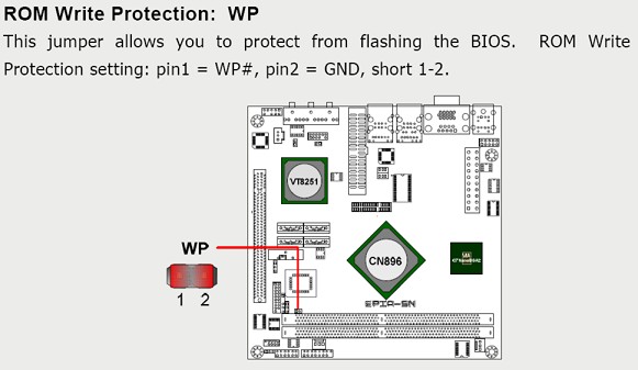
Here's a small little step which had me stumped for a while. Power off the system and remove the BIOS write-protect jumper!
Now power-up the system and press F11 during POST to bring up the boot selection menu and boot from the USB device. If the USB drive does not appear in the boot list you may need to restore the current BIOS configuration to default first or at least ensure that legacy support for USB devices is enabled. Failing that test your bootable USB key on an other system to conform it boots correctly. Failing that you may need to resort to a bootable CD which is also easily made.
Update the BIOS with following command, AFUDOS I1A0D205.ROM /P /B /N /C
During programming you will note that NVRAM is re-written and the checksum is destroyed. This is good!
Remove the USB device and restart the system, ignore CMOS checksum complaint and press F1 to enter BIOS configuration
Load defaults, save & exit.
It's up to you whether or not to re-fit the write protect jumper. I put mine back on again just to be sure.
Credits For This Article
www.via.com.tw for the upgraded BIOS, programming tool and the image used in this document.
http://www.bootdisk.com for information on USB boot.
Seth Purdy (spurdy) at ViaArena for his notes.
Files
AFUDOS.rar - Flash Programming Tool
I1A0D205.ROM - BIOS ROM File 2.50
Wednesday, July 8. 2009
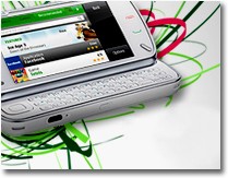
Finding The J-Spot On The Nokia N97
I recently became the proud owner of Nokia's new n97. One of the included trial applications which just blew me away for its 'utility' value is 'JoikuSpot' by Joikusoft.
Please visit my post titled Finding The J-Spot On The Nokia N97 at Innovation Mentor for my thoughts.
...Robert
Please visit my post titled Finding The J-Spot On The Nokia N97 at Innovation Mentor for my thoughts.
...Robert
Wednesday, May 6. 2009
Turbo Charging An Old HP Brio Part II
More than a year ago I converted an old Brio BA600 into a little AMD64x2 rocket. Another of these Brio's fell into my lap so time to do it all again. Fortunately I had kept my notes from last time and as the new motherboard is extensibility the same I was able to follow my instructions to the letter except for a few key points.
This old Brio BAX400 had been shelved for some time its PII-400 cpu, 256MB ram and 4.2GB drive. Not very thrilling but time for some changes.
New motherboard - Gigabyte GA-M61PME-S2P (need uATX form factor)
New CPU - AMD 5200+ dual core (not to much grunt as the PSU can't cope)
New RAM 2 x 2GbDDR2-800, 4GB Total (128bit mode)
New Drives 2 x 1TB 7200rpm SATA 3.0GB/s, 1TB total in RAID1 mirror
All up just over A$500 for a 4GB, 2700Mhz Dual Core, 1TB RAID1 Mirrored server.
Again here's where the fun begins...
The uATX motherboard drops straight into the Brio chassis, so far so good. First hitch, wrong power connector! The old Brio used a 20 pin V1.0 ATX Connector while the new board has a 24 pin V2.0 ATX Connector. Simple solution, just plug into the first part leaving the end 4 pins exposed. See photo.
Next hitch, the board has a 4 pin 12V Aux ATX Connector while the existing PSU has a 6 pin plug with one blue wire running to it. In essence we only need to get a good 12V supply onto one pin of this 4 pin connector as the other 3 are routed back to the main power supply connector. Solution;
a) Cut the blue wire to this 6 pin plug back near the PSU and insulate the remaining blue wire running back in the PSU.
b) Take the blue 6 pin plug and a very sharp knife and convert it into a 4 pin plug (see photo below).
c) Splice/connect the free end single blue wire attached to the plug onto one of the heavy yellow drive wires. (note all drives use 1 yellow, 2 black and 1 red wire per hard drive connector)
d) Plug the new cut down plug into the 4 pin motherboard socket as shown below. Please note very, very, very carefully the orientation of how this connector is fitted. (see photo below) Yes I know it looks very strange! A better solution would be to purchase and use new connectors or re-use old ones but I simply had none and had to make do.
Next are front panel connectors, the bane of any upgraders life! Again some surgical work with the knife split the existing Brio single row connector into the just the right single connectors. (see photo)
Last but perhaps most annoying were the fitting of the RAID1 Array pair of drives. One drive was easy as the Brio has only one location for fitting a hard drive. The second drive was not so easy. Being SATA drives their location is limited to the length of the SATA cables. I could have placed the drive at the top of the chassis but would have had to rearrange the optical drive and I would have lost my spare IDE drive location. My solution was to drive two holes in the chassis spreader bar and mount the second drive as shown.
This machine is now running Ubuntu 8.04 LTS and VMware Server and is destined to host several virtual machines, replace existing real servers, reducing my electricity bill and help do my part in being green. Setting all that up will be a whole new story!
...have fun and enjoy your new Brio! ...Robert
Important notes. The Brio PSU is rated for 90W. Yes that's all so keeping the motherboard and CPU down at the bottom end of speed is very important. Same goes for only using one low power drive and optical drive. In practice that little 90W supply packs a punch more but I would not count on it. Also you follow these instructions at your own risk! Dead motherboards, PSU's and sliced fingers from sharp knives will not be my problem. Although this information is provided in good faith, I can not accept any responsibility for how it is applied.
Sunday, February 17. 2008
Turbo-Charging An Old HP Brio
There comes a time in the life of any old PC when you have to make that hard decision; turf it or turbo it! This old Brio BA600 had served well with its PII-600 cpu, 256MB ram and 4.2GB drive but alas both times and demands have changed. I chose upgrade!
New motherboard - Gigabyte GA-M61SME-S2L (need uATX form factor)
New CPU - AMD 4400 dual core (not to much grunt as the PSU can't cope)
New RAM DDR2-800 2GB (128bit mode)
New Drive 400GB
All up around $300
So here's where the fun begins...
The uATX motherboard drops straight into the Brio chassis, so far so good. First hitch, wrong power connector! The old Brio used a 20 pin V1.0 ATX Connector while the new board has a 24 pin V2.0 ATX Connector. Simple solution, just plug into the first part leaving the end 4 pins exposed. See photo.
Next hitch, the board has a 4 pin 12V Aux ATX Connector while the existing PSU has a 6 pin plug with one blue wire running to it. In essence we only need to get a good 12V supply onto one pin of this 4 pin connector as the other 3 are routed back to the main power supply connector. Solution;
a) Cut the blue wire to this 6 pin plug back near the PSU and insulate the remaining blue wire running back in the PSU.
b) Take the blue 6 pin plug and a very sharp knife and convert it into a 4 pin plug (see photo below).
c) Splice/connect the free end single blue wire attached to the plug onto one of the heavy yellow drive wires. (note all drives use 1 yellow, 2 black and 1 red wire per hard drive connector)
d) Plug the new cut down plug into the 4 pin motherboard socket as shown below. Please note very, very, very carefully the orientation of how this connector is fitted. (see photo below) Yes I know it looks very strange! A better solution would be to purchace and use new connectors or re-use old ones but I simply had none and had to make do.
Last but not least are front panel connectors, the bane of any upgraders life! Again some surgical work with the knife split the existing Brio single row connector into the just the right single connectors. (see photo)
I have confirmed these instructions also apply to Asus motherboard M2N-MX and probably many other uATX form factor motherboards as well.
So after all that I have a new little rocket in an old friendly case and this time its running Linux!
...have fun and enjoy your new Brio! ...Robert
Important notes. The Brio PSU is rated for 90W. Yes that's all so keeping the motherboard and CPU down at the bottom end of speed is very important. Same goes for only using one low power drive and optical drive. In practice that little 90W supply packs a punch more but I would not count on it. Also you follow these instructions at your own risk! Dead motherboards, PSU's and sliced fingers from sharp knives will not be my problem. Although this information is provided in good faith, I can not accept any responsibility for how it is applied.
Monday, February 11. 2008
TomTom Plug-ins
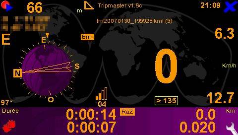
Welcome to the world of TomTom Plug-ins. Be prepared to make, break, fix and play with your TomTom if you venture down this route. The destination? Well that's up to you. Let's just say that looking at a skewed raster image on my screen is not a welcoming sight and that tiny little hole at the base of the unit for resetting is a godsend.
So if you are determined and need to play then try the the plug-ins at Webazar TomTom Pulg-ins for starters.
One final tip which may save some anguish is to play with plug-ins using an external SD card (for those which have them) rather then the TomTom internal memory, otherwise BACK UP before playing.
Until next time keep tinkering! ...Robert
Friday, February 8. 2008
Disabling the F1 Keyboard Prompt on a Compaq Deskpro
The Deskpro series were very well-built, quiet and reliable PCs and they suit the task of a dedicated SOHO server extremely well. Using the default BIOS configuration they however complain bitterly about not having keyboard plugged in. It is most amusing being first told there is no keyboard and then being asked to press 'F1' to continue.
Here are the steps required to run your Compaq with no keyboard or mouse in 'Server Mode'.
1. Press F10 when prompted at startup to enter BIOS setup.
2. Go to the Security menu and select Power-On Password.
3. Assign a password and press F10.
4. In the Security menu, a new option should appear called Password Options.
5. Open this item and set Network Server Mode to Enabled.
6. Save the changes and exit.
The computer will now boot without any prompting and disable the PS/2 keyboard port, turning it into a dedicated server.
If you need to perform maintenance from the console you can press F10 at boot to enter the BIOS setup and enable the keyboard again. You can also plug in a USB keyboard and it will work normally while the operating system is running. In this mode a BIOS setup password is also recommended. My preferred method however is to use a remote desktop tool such as VNC Server/Viewer to provide remote management.
Older Deskpros that do not support network server mode need a 'No F1 Bios Patch' from Compaq to kill the F1 prompt. Even though I have used this patch successfully on three different Compaq machines, I have only provided this as a convenience and will not accept any responsibility for any damage done to your computer.
Have fun with this, ...Robert
Sunday, January 27. 2008
How To Confuse A Nokia n80 Firmware Upgrade
I have spent a frustrating 8 months with buggy software in my Nokia n80. My biggest problem is that sometimes the phone's power management would flatten the battery in 2hours while supposedly on standby!
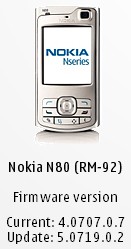
For some months the Nokia Software Update program was telling me there was new firmware but would crash any time I tried to download it. The for the last 5 months it told me my software actually was up to date. So here I was stuck with version 4.0707.0.7 when the Nokia forums were telling me there was new software.
Some background... 12 months ago I reflashed my Nokia n80 with n80i firmware and replaced the original device code (00539815) with one of the n80i Australian codes 0540864 (AUSTRALIA Smooth Stainless Internet Edition). Today I contemplated the fact that all real n80i's I had seen were black. So I reprogrammed the device code with 0540843 (AUSTRALIA Pearl Black Internet Edition) and tried again.... SUCCESS!!!
I am now the proud owner of a nokia n80 pretending to be a nokia n80i with software version 5.019.0.2. Time to re-install all my widgets into it again!
For those wanting to tinker, the tool used reflash the device ID can be found at http://rapidshare.com/files/5911866/nss10383.rar
1. Install NSS and run
2. Plug in phone and select "pc suite" on phone
3. In NSS click "scan for new devices"
4. Click phone info
5. Click enable product code and enter 0540843 (this is for AUSTRALIA Pearl Black)
6. Click "write"
7. When complete unplug phone and exit NSS
8. Uninstall NSS
More information including device codes for other regions and countries can be found at http://www.allaboutsymbian.com
Happy tinkering! ( at your own risk with no responsibility accepted by me! )
... Robert
« previous page
(Page 2 of 3, totaling 34 entries)
next page »