I have since replaced the original Motormarine cable with a Nikonos style connector using just the GND and X-SYNC pins in order to use with a housed camera. This was OK but I was limited to full power on every operation which lead to many frustrated photo dives. I had always intended to modify the strobe in order that the TTL switch could be used to reduce the strobe power to a fixed reduce power, for example 1 or 2 stops below full power.
I had put off making this modification for two reasons;
a) I could not find anywhere on the internet a full circuit diagram for the YS-50TTL strobe, and
b) reverse engineering the strobe myself would be a time consuming process.
In the end I chose step b) which involved recreating the circuit diagram by both tracing the board, its components and downloading component data for various devices. The only parts I was not able to identify the actual data for where the step up transformer, the trigger transformer and the flash tube. For the transformers I have made my best guess at their internal configuration.
The resulting circuit diagram presented here is my best effort which may include errors or omissions and I accept no responsibility for how this may be used. It serves my purpose of understanding how the strobe works including the TTL mechanism and enabled me to work out the modifications required to use the TTL switch for a fixed reduced power level.

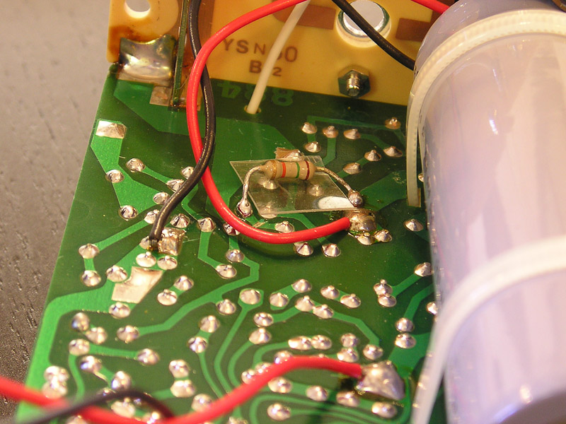
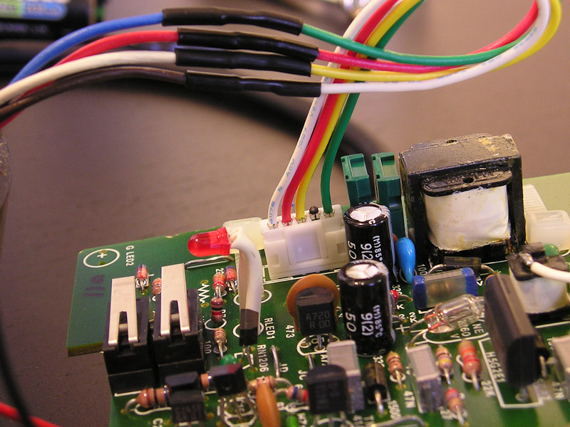
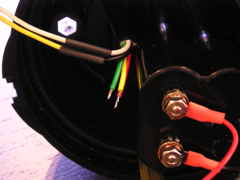
There are two modifications identified on this circuit diagram. The first is the Fast Fire modification (http://www.devilgas.com/diving/ys50ttl/ys50ttl.asp) which I originally made a few years ago although it is not really necessary for a manual single fire strobe application. I have only included it because I have already made this change.
Fast Fire Modification
Here are my images for this modification as I approached it a little differently from the modification shown by DevilGas. Notice that rather than lift the diode off the PCB I have cut the PCB track instead to leave the diode in place on the PCB.


Manual Power Control Modification
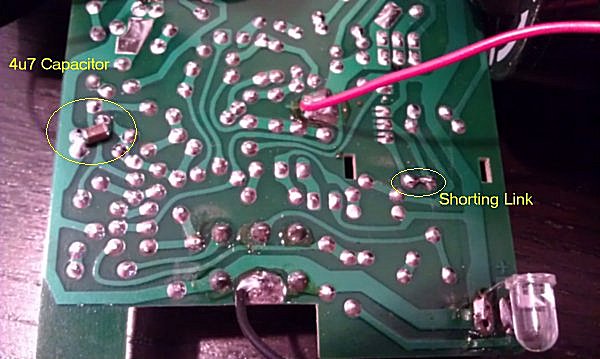
The second modification shown in the circuit diagram at the bottom right shows my solution to implement a reduced power setting via the TTL switch. The circuit shows a number of capacitor values which correspond to selectable power levels and and light outputs of -0.5, -1, -2 and -4 stops below full power. I have chosen 4u7 which creates -2 stops (or halves the guide number from 24 to 12).
Here are my images for this modification which you can appreciate are trivial.

Important Disclaimer
This information is provided purely to document my modifications and carries no implied warranty for either correctness of content or any consequence arising from its use by anyone else.
High power strobes used dangerous high voltage electronics and 300VDC or more may be charged and ready to bite (potentially fatally) even if the strobe is turned off.
Further more, modification such as these have the potential to destroy your precious digital camera if not implemented correctly and I accept no responsibility for any event arising.
... Robert Rath 3/8/2012
References For This Article
http://www.devilgas.com/diving/ys50ttl/ys50ttl.asp
http://www.camerasunderwater.co.uk/ttl-flash-interface
Files


