Robert’s Gadget Zone

toys are are only interesting when you play with them in ways the toymaker never expected!

How To Resize An Encrypted Drive

In these examples we will expand the entire disk from 32GB to 64GB.

The examples given are with and without an existing swap volume and will use an Ubuntu Live CD ISO as the surrogate.

  • Shutdown the target machine.

  • In VMware Player, select the target and go to ‘Edit virtual machine settings’.

  • Select the ‘Hard Disk’ and then go to ‘Utilities -> Expand…’.

  • Enter the new size, ie 32GB and click on ‘Expand’.

  • Select the ‘CD/DVD’, ensure ‘Connect at power on’ is checked, select ‘Use ISO image file:’ and browse for an approriate Live CD ISO file to boot from. Click OK.

  • In VMware Player, select the target and start it. Ensure you are booting into the Live CD.

  • If the boot is incorrect, append the line ‘bios.forceSetupOnce = “TRUE”‘ to your target ‘vmx’ file, make the necessary bios changes and then boot into the Live CD.

  • Make sure you select ‘Try Ubuntu’ and NOT install.


  • root@ubuntu:~# lsblk


  • Now that we have identified sda as our target we can go to work on it. Proceed with caution as you can easily destroy all your data!


  • fdisk /dev/sda # open sda in 'fdisk'


  • Use the ‘p’ command to print the current partition table, note the start sector addresses of both sda2 and sda5.

  • Use the ‘d’ command to delete partitions 5 and then 2.

  • Use the ‘n’ command to create a new extended partition 2. Use the default sector start address which may be less than the original sda2.

  • Use the ‘n’ command to create a new logical partition 5. Make sure the sector start address is exactly the same as the original sda5. Do not remove the LUKS signature if asked.

  • Use the ‘w’ command to write the changes and exit from ‘fdisk’.

  • The system may automatically mount sda1/sda5 during operations. If so unmount them.


  • Simple Single Volume

    In this example we will expand the entire disk from 32GB to 64GB.

    cryptsetup luksOpen /dev/sda5 target    # use the LUKS password to decrypt sda5
    vgscan --mknodes && vgchange -ay        # Identify and activate the LVM.
    cryptsetup resize target                # Resize the crypt
    pvresize /dev/mapper/target             # Resize the volume group
    pvchange -x y /dev/mapper/target        # unlock the (LVM) physical volume.
    lvresize -r -L+32G /dev/xubuntu-vg/root # increase our root volume by in this case 32GB, resizing (-r) the underlying filesystem 
    vgdisplay                               # find out how much space is now available in our volume group
    pvchange -x n /dev/mapper/target        # re-lock the physical volume
    shutdown -h now                         # we are done with the Live CD so.


    Include A Swap File

    In this example we will expand the entire disk from 32GB to 64GB moving an existing swap file of 4GB to the end of the drive.

    cryptsetup luksOpen /dev/sda5 target                         # use the LUKS password to decrypt sda5
                                                                 # the system may automatically mount sda and the logical volumes
                                                                 # inside target_encrypted_volume. If so unmount them.
    vgscan --mknodes && vgchange -ay                             # Identify and activate the LVM.
    cryptsetup resize target                                     # Resize the crypt
    pvresize /dev/mapper/target                                  # Resize the volume group
    lvdisplay                                                    # Use 'lvdisplay' to identify the target volumes for managing
    lvremove /dev/xubuntu-vg/swap                                # remove our swap volume, it is in the way.
    pvchange -x y /dev/mapper/target                             # unlock the (LVM) physical volume.
    lvresize -r -L+32G /dev/xubuntu-vg/root                      # increase our root volume by in this case 32GB, resizing (-r) the underlying filesystem 
    vgdisplay                                                    # find out how much space is now available in our volume group
    lvcreate --extents 1024 -n /dev/xubuntu-vg/swap   xubuntu-vg # Create a new volume (516 comes from finding the available 'logical extents' in the group using 'vgdisplay'). Remove Swap signature
    pvchange -x n /dev/mapper/target                             # re-lock the physical volume (may be redundant) 
    mkswap /dev/xubuntu-vg/swap                                  # make the new 4GB volume a swap volume. Copy the UUID to the clipboard. 
    lvdisplay                                                    # Use 'lvdisplay' to check our new volumes look good. 
    lsblk                                                        # final sanity check 
    shutdown -h now                                              # we are done with the Live CD


  • Edit the target machine to disconnect the CDROM at startup.

  • Start the target machine and check all changes work as intended.


  • References Used

    https://linux.die.net/man/8/lvcreate
    http://www.systemadminihater.com/linux/split-a-lvm2-volume-group-into-two-or-more/
    http://www.thegeekstuff.com/2010/08/how-to-create-lvm
    https://linux.die.net/man/8/lvresize
    http://tldp.org/HOWTO/LVM-HOWTO/removelv.html
    https://help.ubuntu.com/community/ResizeEncryptedPartitions
    http://askubuntu.com/questions/63594/mount-encrypted-volumes-from-command-line

    DJI Mavic 2 – ATTI Mode

    I used the the following reference for this modification to the Mavic 2 however it does not work for a Windows user so here is my version.

    https://www.thedroneu.com/blog/atti-mode-mavic-2-pro-hack-zoom/

    1. Download and install DJI Assistant 2 v1.1.2

    https://www.mavichelp.com/Mavic-2#SoftwareArchive
    https://www.sekidorc.com/press/DJI_Assistant2_Installer_v1.1.2_20170527.zip

    2. On Windows edit line 113 of “C:\Program Files (x86)\DJI Product\DJI Assistant 2\AppFiles\main.js” to uncomment the line
    mainWindow.webContents.openDevTools()

    3. Open DJI Assistant 2 (do no open DJI Assistant 2 for Mavic if you also have a later version installed)

    4. Referencing the instructions at https://www.thedroneu.com/blog/atti-mode-mavic-2-pro-hack-zoom/ make the following modification to ‘fswitch_selection_2|g_config_control_control_mode[2] from 7 to 3.

    Default configuration

    fswitch_selection|g_config_control_control_mode[0] 12 = Tripod Mode
    fswitch_selection_1|g_config_control_control_mode[1] 8 = Positioning Mode
    fswitch_selection_2|g_config_control_control_mode[2] 7 = Sports Mode

    Note we have modified the third switch position which was Sport mode (7) with ATTI mode (3)

    Dock Cheat Sheets – Ubuntu 18.04 Fast Docker Installation

    Install Docker Engine – Community
    =================================

    ref: https://docs.docker.com/install/linux/docker-ce/ubuntu/
    ref: https://docs.docker.com/install/linux/linux-postinstall/

    $ sudo apt-get update # update the apt package index:
    $ sudo apt-get install apt-transport-https ca-certificates curl gnupg-agent # install packages to allow apt to use a repository over HTTPS:
    $ sudo apt-get install software-properties-common # install packages to allow apt to use a repository over HTTPS:
    $ curl -fsSL https://download.docker.com/linux/ubuntu/gpg | sudo apt-key add – # add Docker’s official GPG key:
    $ sudo apt-key fingerprint 0EBFCD88 # verify that you now have the key with the fingerprint …
    $ sudo add-apt-repository “deb [arch=amd64] https://download.docker.com/linux/ubuntu $(lsb_release -cs) stable” # set up the stable repository
    $ sudo apt-get update # update/refresh the apt package index:
    $ sudo apt-get install docker-ce docker-ce-cli containerd.io # install the latest version of Docker Engine
    $ sudo docker run hello-world # verify the Docker Engine installation
    $ sudo groupadd docker # create the docker group if not already present
    $ sudo usermod -aG docker $USER # add your user to the docker group
    $ newgrp docker # activate the changes to groups:
    $ docker run hello-world # verify the Docker Engine installation without sudo
    $ sudo systemctl enable docker # configure Docker to start on boot

    Cross Compiling The RaspberryPi Linux Kernel


    These are a jumbled set of notes as I worked my way through downloading and building the Pi linux kernel from source code.

    References

    #ref: http://blog.eihis.com/?p=423
    #ref: http://simonthepiman.com/how_to_setup_windows_file_server.php
    #ref: http://www.raspberrypi.org/phpBB3/viewtopic.php?f=66&t=57401
    #ref: http://elinux.org/RPi_Kernel_Compilation#Get_the_kernel_source

    On Pi

    apt-get update
    apt-get dist-upgrade
    apt-get install build-essential
    apt-get install module-assistant
    m-a prepare
    wget http://blog.eihis.com/wp-content/uploads/2013/07/linux-headers-3611_3611-2_armhf.deb
    dpkg -i http://blog.eihis.com/wp-content/uploads/2013/07/linux-headers-3611_3611-2_armhf.deb
    ln -s /usr/src/linux-headers-3.6.11+ /lib/modules/3.6.11+/src
    ln -s /usr/src/linux-headers-3.6.11+ /lib/modules/3.6.11+/build
    apt-get install samba
    apt-get install samba-common-bin
    m-a prepare

    On Ubuntu

    git clone -b rpi-3.10.y https://github.com/raspberrypi/linux.git
    cd linux
    git checkout master
    git checkout rpi-3.6.y
    export KERNEL_SRC=/home/robert/raspberry-pi/src/linux/
    cd /home/robert/raspberry-pi/
    git clone https://github.com/raspberrypi/tools
    export CCPREFIX=/home/robert/raspberry-pi/tools/arm-bcm2708/arm-bcm2708-linux-gnueabi/bin/arm-bcm2708-linux-gnueabi-
    cd /home/robert/raspberry-pi/src/linux/
    make mrproper
    scp root@192.168.10.31:/proc/config.gz ./
    gunzip config
    mv config .config
    make ARCH=arm CROSS_COMPILE=${CCPREFIX} oldconfig
    make ARCH=arm CROSS_COMPILE=${CCPREFIX} menuconfig
    export MODULES_TEMP=/home/robert/raspberry-pi/modules/
    make ARCH=arm CROSS_COMPILE=${CCPREFIX} INSTALL_MOD_PATH=${MODULES_TEMP} modules_install
    cd /home/robert/raspberry-pi/tools/mkimage
    ./imagetool-uncompressed.py ${KERNEL_SRC}/arch/arm/boot/zImage
    cd /home/robert/raspberry-pi/modules/lib/
    tar -czvpf firmware+modules.tar.gz ./firmware ./modules
    scp firmware+modules.tar.gz root@192.168.10.31:/lib/

    On Pi

    cd /boot
    mv kernel.img kernel_original.img
    mv fixup.dat fixup_original.dat
    mv start.elf start_original.elf
    mv bootcode.bin bootcode_original.bin
    cd /opt
    tar -czvpf vc_original.tar.gz ./vc
    rm -fR vc
    cd /lib
    tar -czvpf firmware+modules_original.tar.gz ./firmware ./modules
    tar -xzvpf firmware+modules.tar.gz

    On Host

    cd /home/robert/raspberry-pi/
    git clone https://github.com/raspberrypi/firmware
    cd /home/robert/raspberry-pi/firmware
    git checkout next # d4f5315cfac4e was current on my pi before being overwrit
    cd /home/robert/raspberry-pi/firmware/boot
    scp bootcode.bin fixup.dat start.elf root@192.168.10.31:/boot/

    cd /home/robert/raspberry-pi/tools/mkimage
    scp kernel.img root@192.168.10.31:/boot/
    ${CCPREFIX}gcc -v 2>&1 | grep hard # check for hard float, even though came back as soft it looks like the board need hard!
    cd /home/robert/raspberry-pi/firmware/hardfp/opt
    tar -czvpf vc-hard.tar.gz ./vc
    scp vc-hard.tar.gz root@192.168.10.31:/opt/

    On Pi

    cd /opt
    tar -xzvpf vc-hard.tag.gz

    Update

    # I packaged up the linux kernel source and moved them to the pi and compiled locally

    On Host

    cd /home/robert/raspberry-pi/src
    tar -czvpf linux.tar.gz ./linux
    mkdir tmp
    cd tmp
    tar -xzvpf ../linux.tar.gz
    cd linux
    make mrproper
    rm -fR ./.git
    rm ./.gitignore
    cd ..
    tar -czvpf linux.tar.gz ./linux
    scp linux.tar.gz root@192.168.10.31:/usr/src/

    On Pi

    cd /usr/src
    rm linux
    tar -xzvpf ../linux.tar.gz
    cd linux
    cp /proc/config.gz .config.gz
    gunzip .config.gz
    apt-get install ncurses-dev
    make oldconfig
    make menuconfig
    make # commenced at 12:52 (13:10 for cross host)

    … Robert


    Testing a New Proxy Configuration

    I discovered an issue with the proxy server and the URL re-write rule used to access the RaspberryPi. This blog entry is testing the ability to externally comment. Thanks to Dan Johnson for taking the time to let me know there was an issue.

    New Thinking For a Bullet Proof Solution

    I have not done any work on this for some months now so am eager to pick it up again.

    My thinking for this project has changed as I have worked out that using the Pi to directly control the active appliance peripherals will not work for two reasons.

    a) There are no native analog inputs which are required for temperature measurements, and
    b) There is a need to maintain fail-safe interlock protections and I do not trust the RaspberryPi/Linux platform to operate at the level of unbroken reliability required.

    I have researched and sourced a small Atmel based Arduino board which will virtually drop into the main control PCB as a replacement for the existing OTP micro-controller. I plan to program this device to emulate the existing program or pass control over to the RaspberryPi but still take back control in the event the RaspberryPi application were to fail or attempt to do anything unsafe.

    A simple serial interface back to the Pi (possible optically coupled for main isolation).

    This gives me the best of all solutions, a fail-safe local controller which will work independently of the Pi but also allow the Pi to take over operations in a safe and controlled manner.


    … more to come.


    Raspberry Power To The Coffee Machine

    Getting back to my original idea of Raspberry Pi powering my coffee machine I started reverse engineering the sensors in investigating the required inputs and outputs.

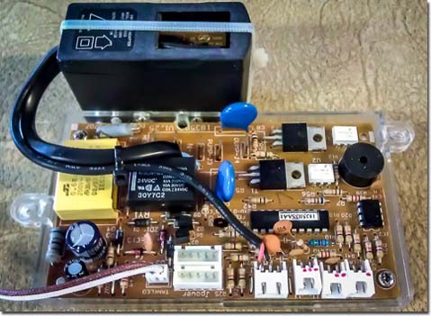
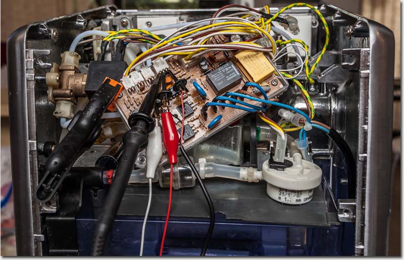
    This image shows the main control board removed from its normal location and placed connected with inputs and outputs accessible.


    One thing I quickly noted was that the entire ELV (Extra Low Voltage) circuit was references to the mains active supply line. This required just a little bit of care in making any measurements.

    Measurements with a multimeter are generally not a problem as they are generally very well insulated but I need to use a DSO (Digital Storage Oscilloscope) for some of the measurements and my DSO was an earthed piece of equipment. I could have supplied the coffee machine using an isolation transformer but the heating cycle would overload it. Instead I chose to isolate the DSO and float it to mains active potential for all measurements. In this was I was able to determine the logical levels, thermistor resistor measurements against heating block temperature and the the flow-meter performance.

    Flow Meter

    The flow meter was found to deliver around 2140 pulses per litre unobstructed and 2368 working in the optimum pressure region. From this I note two points, a) that the flow meter is non linear and more testing will be needed to create an accurate count per litre to flow rate calibration, and b) the existing firmware uses flow-rate information as a proxy for pressure measurement in order to back off on the pump. The flow-meter input drives and interrupt pin on the micro’.

    Temperature Metering

    The temperature measurement is made using a 100K NTC device mounted on the heating block. Initial testing show the heating block is cycled for input voltages at the micro’ of 2.31 (on) ans 2.12 (off) for a supply of 5.2V. From this I will be able to source the thermistor data assuming a block target temperature of 90degC.

    Logic

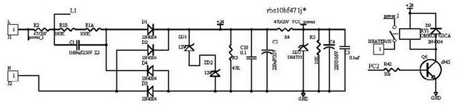
    The logic for the control of the pump, heater and discharge solenoid are simple outputs however all other logic comprises 6 multiplexed switch/led combinations where echo IO pin operate the LED and reads the input switch via multiplexing between input and output operations. See BES820XL.pdf for the full schematic details.

    Power Supply

    This is the first major issue to need an overhaul. The design uses a low cost capacitive supply and from a long experience in this kind of design I can only say that it needed to be replaced with a real supply if it would ever power the Raspberry Pi with WiFi.


    I retained the 24VDC supply for the relay (for now), removed R4 and inserted a 5V 1000mA SMPS. That should be more than enough! 🙂


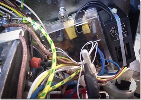
    Here is the control board back into position for an extended period of trial in this configuration while I consider the next steps.


    … Robert


    New WiFi Adpater

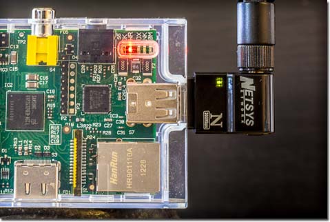
    I needed another Netsys 300N adapter for a different project. When I received it the form factor had changed so I decided to use the new smaller adapter for the ‘Pi instead.


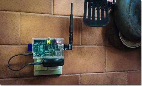
    Here now with it’s new profile is the ‘Pi running all on it’s own on the kitchen wall ( delivering this webpage! )


    … Robert


    Using the Spyder Express On Multiple Monitors

    I have been using my trusted Spyder3 Express in a WindowsXP environment for a few years now to calibrate my monitors and ensure consistent colour and tone rendering between computers. Recently however I upgraded to a new Windows7 dual monitor desktop and officially the Spyder3 Express no longer worked for me.
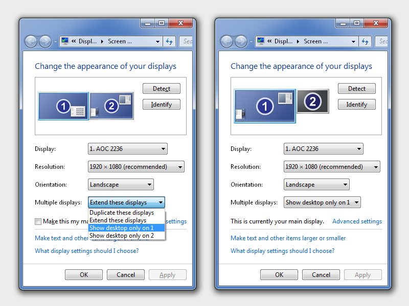
    Looking for help on this issue I kept getting the same message that I need to pay double for the model which does support multiple monitors. The ‘Express’ is an inexpensive entry level product designed only to support a single monitor.

    Rather than being forced to pay for an upmarket product with multiple monitor support I decided to find a work-around. Here is my successful solution providing monitor independent calibration for two monitors, an AOC and a BENQ. I apologize for this rather terse set of instructions. Feel free to ask questions if this does not work for you.

    Step 1. – Get your dual monitor desktop configured and working the way you want.
    Step 2. – Install the SpyderX Express drivers and software but do not begin any calibration.
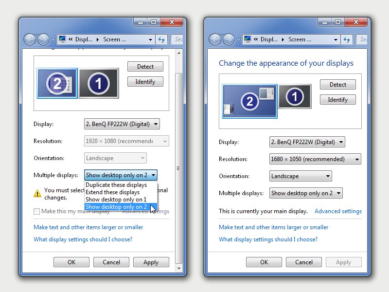
    Step 3. – Go into Screen Resolution settings (right click on the desktop) and change the display to only use monitor 1 as shown.

    Step 4. – Perform a standard SpyderExpress calibration procedure on the selected monitor and confirm colour has been corrected as expected.
    Step 5. – Using file explorer, navigate to the profiles directory ‘C:\Windows\System32\spool\drivers\color’.
    Step 6. – Locate the newly created file ‘Spyder3Express.icm’ and make a copy of it in the same directory, in my case ‘Spyder3Express-AOC2236-20121005.icm’.
    Step 7. – Repeat Steps 3-5 as above but this time select monitor 2 as shown below and calibrate it in the same way.

    Step 8. – Locate the new ‘Spyder3Express.icm’ file for the second monitor and make a copy of it in the same directory, in my case ‘Spyder3Express-FP222W-20121005.icm’.

    The next part is a little tricky and may be dependent on the menus in your graphics setup.

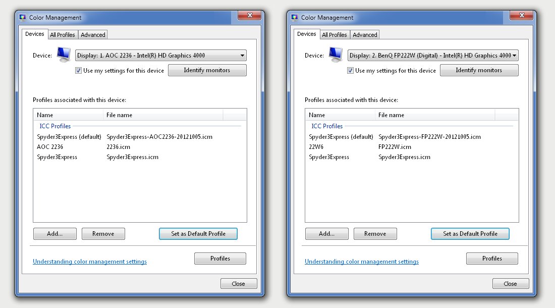
    Step 9. – Go into Screen Resolution settings (right click on the desktop), click on ‘Advanced settings’, select the ‘Color Management’ tab and click on the ‘Color Management…’ option.
    Step 10. – Select the ‘Device:’ monitor 1 and make sure the check box ‘Use my settings for this device’ is selected.
    Step 11. – Click ‘Add..’ and navigate through the list of profiles to find the profile you created for monitor 1 using the ‘File name’, not the profile ‘Name’.
    Step 12. – With the new profile for monitor 1 now in the profiles list, ‘Set as Default Profile’.
    Step 13. – Repeat Steps 9-12 for monitor 2 and confirm setting are similar to those shown below.


    Step 14. – Exit the graphics menus and confirm the new independent calibrations can be enabled and disable using the SpyderExpress system tray tool.

    Yes it’s a little messy but you really do not need the more expensive multiple monitor version. The ‘Express’ will do multiples just fine.

    … Robert