Robert’s Gadget Zone

toys are are only interesting when you play with them in ways the toymaker never expected!

Backing Up The Entire Raspberry Pi

Prior to attempting to run my ‘Pi at 1000Mhz I decided it would be a good idea to backup the entire machine.

As it uses a 4GB SD it made sense to use another 4GB card as the backup destination. As it turns out it was simpler than I expected.

I placed a new 4GB SD card in a USB card reader and inserted into on of the ‘Pi’s USB ports. I then checked to see what device node the ‘Pi used for the card. In my case I found the card at ‘/dev/sda’, and that it has not been automatically mounted. In my case it was not automatically mount but other/future version of ‘wheezy’ may do this so it is important to use the ‘mount’ command to check this.

The following command line shows how I block copied the entire content on the operating system block device ‘/dev/mmcblk0’ to the unmount SD card at ‘/dev/sda’.

sudo dd if=/dev/mmcblk0 of=/dev/sda bs=4M

root@raspberrypi:/boot# dd if=/dev/mmcblk0 of=/dev/sda bs=4M
945+1 records in
945+1 records out
3965190144 bytes (4.0 GB) copied, 840.205 s, 4.7 MB/s


To test I simply placed the new card into the Raspberry Pi and up it came, a perfect clone!

As it turns out, my ‘Pi failed to start at 1000Mhz 🙁 so the effort was well worth it :-).


… Robert

Need More RAM

Today I discovered my Pi had gone off-line! No WEB, no SSH. I am not sure what happened but a reboot brought it back to life again.

So while it had my attention I decided a few tweaks were in order.

Tweak 1. More RAM

During general operations I had previously noticed MySQL had grabbed a substantial chunk of virtual memory and on a NAND based system this is not desirable. I am not sure how the memory was being used but seeing I am not using HDMI video I could reconfigure the Pi to use less video memory and give more back to user space applications.

In my case I copied ‘/boot/arm240_start.elf’ to ‘/start.elf’ which immediately gave me back a much needed extra 48M of RAM.

Tweak 2. Bump Up The Speed

I edited the ‘/boot/config.txt’ file to enable CPU overclocking beginning at 800Mhz initially to see how that goes.

#uncomment to overclock the arm. 700 MHz is the default.
arm_freq=800


I like the raspberry coloured gear graphics I found so I may use this for all general configuration tweaking posts.


… Robert


Backing Up the Raspberry Pi Blog

It would be a shame to lose everything I have put into the Raspberry Pi blog so it’s time to put in a backup regime.


Strategy

The Raspberry Pi blog is located both both ‘/var/www/raspberrypi/’ and in the serendipity-db catalog of the local MySQL database. We will need to backup up both to completely cover ourselves.

The strategy for backup will be to make archives of both the filesystem and the mysql database, archive them together and then copy to the network drive under a unique filename. The backup will be run from a script which which will live in the ‘/var/www’ directory and be regularly run from an entry in the ‘/etc/crontab’ file.

During the backup process I will create temporary files on the network drive to avoid wear on the local SD card.

We first setup NFS or SAMBA networking and ensure we have mounted our network storage device at a suitable mount point. I have chosen NFS in this example. To use Windows networking adapt the instructions below accordingly.

1. Install NFS client (checked already installed as part of the Weezy distribution).
2. Make a mount point for backups at ‘/var/www/backup’ and add edit ‘/etc/rc.local’ to mount our external resource on boot by adding the following line ‘mount -t nfs -o nolock [IP address or hostname of your NAS server]:/var/local/www /var/www/backup’


Backup Script

Here is my script. Note the use of the file ‘/var/www/backup/sync_www’ to ensure we have mounted the network drive and are not just working with our local mount point.

#!/bin/sh

if [ -e /var/www/backup/sync_www ]; then

mkdir -p /var/www/backup/raspberrypi/
cd /var/www/
tar –exclude-vcs -czf ./backup/raspberrypi/raspberrypi-www_`date +%y_%m_%d`.gz raspberrypi && \
mysqldump -u YOUR_MYSQL_USERNAME_HERE -pYOUR_MYSQL_PASSWORD_HERE serendipity-db | gzip > ./backup/raspberrypi/raspberrypi-mysqldump_`date +%y_%m_%d`.gz && \
tar –remove -cf ./backup/raspberrypi/raspberrypi-blog_`date +%y_%m_%d`.tar ./backup/raspberrypi/raspberrypi-www_`date +%y_%m_%d`.gz ./backup/raspberrypi/raspberrypi-mysqldump_`date +%y_%m_%d`.gz

exit 0

else

exit 1

fi


A brief description pf the steps of the script are as follows

1. Check to see we have mounted the network drive by looking for a file called ‘sync-www’ which we have alread place on the network drive.
2. Create our target backup directory if it does not already exist.
3. Change to the ‘/var/www/’ as our working directory.
4. Create a dated temporary archive of the files in ‘/var/www/raspberypi’
5. Create a dated temporary archive of the mysql data dumped from the catalog ‘serendipity-db’
6. Create the final backup archive removing the temporary working files.


Handling Erorrs

Note the use of ‘&& \’ after each line ensures that the next line only executes if the previous command was successful otherwise the script exits with error code 1.

Note this script could be further enhanced with email notifications of success or failure as needed.


Scheduling

Finally the following entry in ‘/etc/crontab’ will ensure this script runs daily at 2:30 am.

’30 2 * root /var/www/backup-www.sh &’


… Robert


Wi-Fi Pi


Putting the Raspberry Pi into an appliance means that it will not have access to an Ethernet connection and will require USB WiFi.

Which USB Wifi Device?

Adding USB WiFi to a Linux device is generally quite easy however there are limitations which apply to non PC (non x86) applications such as the ARM11 based Raspberry Pi.

The chipset in the WiFi device selected for the Raspberry Pi must be one already supported for the ARM11 device. Simply relying on a chipset vendor to claim Linux support is not enough as this may really mean PC based x86 Linux only. True Linux support means the chipset vendor has made driver source code available to be built for any target CPU.

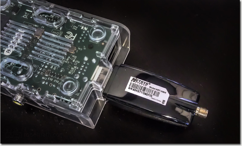
Two of the best supported chipset vendors are Ralink and Realtek. For my application I have used the ‘Netsys Wireless N Model: NET300N’ based on the Realtek 8191SU chipset which already as Raspberry Pi driver support using the Realtek r8712u driver.

This USB WiFi device is available from http://dealextreme.com for about $10.

Making It Work

The following two resources provided the general guidelines I used to get the WiFi up and running in my network.

http://mitchtech.net/realtek-wireless-dongle-rt3070-on-the-raspberry-pi/
http://ubuntuforums.org/showthread.php?t=571188

I installed ‘lshw’ ( apt-get install lshw ) which provides diagnostic information about hardware drivers however as this installation went so smoothly I am not sure this was absolutely necessary.

root@raspberrypi:~# lshw -C network
-network:0
description: Wireless interface
physical id: 1
bus info: usb@1:1.2
logical name: wlan0
serial: 00:0f:11:66:16:d0
capabilities: ethernet physical wireless
configuration: broadcast=yes driver=r8712u multicast=yes wireless=unassociated
-network:1
description: Ethernet interface
physical id: 2
logical name: eth0
serial: b8:27:eb:45:84:2e
size: 100Mbit/s
capacity: 100Mbit/s
capabilities: ethernet physical tp mii 10bt 10bt-fd 100bt 100bt-fd autonegotiation
configuration: autonegotiation=on broadcast=yes driver=smsc95xx driverversion=22-Aug-2005 duplex=full firmware=smsc95xx USB 2.0 Ethernet ip=192.168.10.31 link=yes multicast=yes port=MII speed=100Mbit/s

After manually confirming the following command lines brought up my network,

ifconfig wlan0 down
dhclient -r wlan0
ifconfig wlan0 up
iwconfig wlan0 essid “MYESSID”
iwconfig wlan0 key MYKEY
iwconfig wlan0 mode Managed
dhclient

I then copied thew into ‘/etc/rc.local’ so that the WiFi network would be brought up on boot. An important point for me was that the web article suggests adding the line ‘ifconfig eth0 down’ to the ‘/etc/rc.local’ file but this would mean that hardwired ethernet would be shutdown and not available should it be needed in an emergency.

The final changes I need to make were to my DHCP server and router configuration so that the ‘Pi’ always gets a fixed IP address assigned for correct virtual server port forwarding.

Next Steps

You might notice the nice plastic case (from Element14) in the image which will protect the ‘Pi’ from and ongoing development accidents!
I will now run this setup for a while and look for general stability as a WiFi based web host.

…Robert


Raspberry Latte


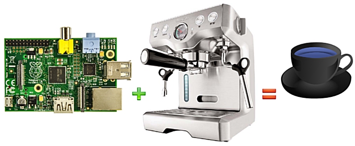
What do you get if you cross a Raspberry Pi with a Breville 820ES Espresso machine? A Raspberry Latte!

There has been a long standing symbiotic relationship between engineers and coffee!! So it only seems natural that a candidate project for my espresso machine is a Raspberry Pi brain transplant. Of course I’ll keep the blog on the coffee machine, it seems appropriate!

I see the project running something like this.

1. Acquire the circuit diagram and study to understand issues such aspower supplies and interfaces.
2. Reverse engineer the control processes currently operating on the espresso machine.
3. Design a suitable interface.
4. Implement WiFi on the Raspberry Pi to avoid running cat5 to the coffee machine.
5. Develop a suitable coffee machine application.
6. Develop a suitable web based interactive application

Some issues I see.

1. Failure mode safety management (circuit design).
2. Electrical isolation between the Raspberry Pi and the high voltage electrical devices.
3. Physical space and form factor.
4. Being without coffee during key development steps, ie keeping the coffee flowing during modifications.

… Robert

BES820XL.pdf


Pi For Dessert


Welcome to my Raspberry Pi!

Last week I ordered a new toy, one little Raspberry Pi and this blog will be dedicated to all the things I do with it.

As can be expected the first thing I did was to put a standard image on an SD card and bring it to life. It gladly obliged with beautiful 1920×1080 hdmi graphics. No surprises so far.

Next I decided that the ideal place for this blog to live is on the Rasberry Pi itself. So after installing and configuring LAMP we are off and running with this little blog being entirely served by the tiny little Raspberry Pi you see in this photo.


Enjoy my Pi, … Robert Rath

How To Modify Sea & Sea YS-50TTL For General Non-TTL Use

I had a Sea & Sea YS-50TTL strobe which was once use with the Motormarine II Camera. This strobe implemented TTL control through the camera metering in order to limit strobe power for correct exposure.

I have since replaced the original Motormarine cable with a Nikonos style connector using just the GND and X-SYNC pins in order to use with a housed camera. This was OK but I was limited to full power on every operation which lead to many frustrated photo dives. I had always intended to modify the strobe in order that the TTL switch could be used to reduce the strobe power to a fixed reduce power, for example 1 or 2 stops below full power.

I had put off making this modification for two reasons;

a) I could not find anywhere on the internet a full circuit diagram for the YS-50TTL strobe, and
b) reverse engineering the strobe myself would be a time consuming process.

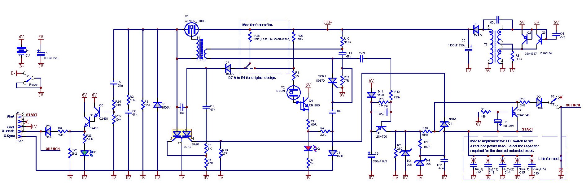
In the end I chose step b) which involved recreating the circuit diagram by both tracing the board, its components and downloading component data for various devices. The only parts I was not able to identify the actual data for where the step up transformer, the trigger transformer and the flash tube. For the transformers I have made my best guess at their internal configuration.

The resulting circuit diagram presented here is my best effort which may include errors or omissions and I accept no responsibility for how this may be used. It serves my purpose of understanding how the strobe works including the TTL mechanism and enabled me to work out the modifications required to use the TTL switch for a fixed reduced power level.


There are two modifications identified on this circuit diagram. The first is the Fast Fire modification (http://www.devilgas.com/diving/ys50ttl/ys50ttl.asp) which I originally made a few years ago although it is not really necessary for a manual single fire strobe application. I have only included it because I have already made this change.

Fast Fire Modification

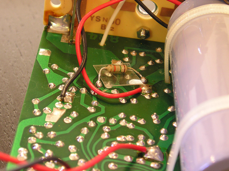
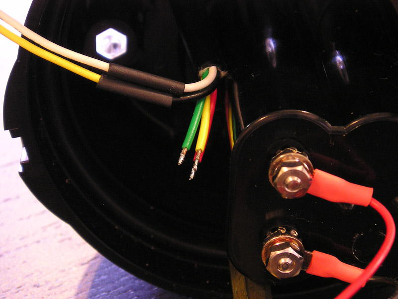
Here are my images for this modification as I approached it a little differently from the modification shown by DevilGas. Notice that rather than lift the diode off the PCB I have cut the PCB track instead to leave the diode in place on the PCB.


Manual Power Control Modification

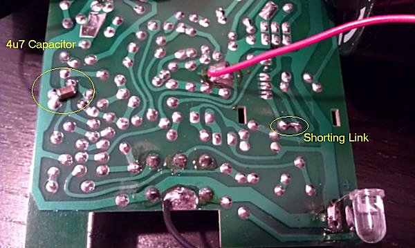
The second modification shown in the circuit diagram at the bottom right shows my solution to implement a reduced power setting via the TTL switch. The circuit shows a number of capacitor values which correspond to selectable power levels and and light outputs of -0.5, -1, -2 and -4 stops below full power. I have chosen 4u7 which creates -2 stops (or halves the guide number from 24 to 12).

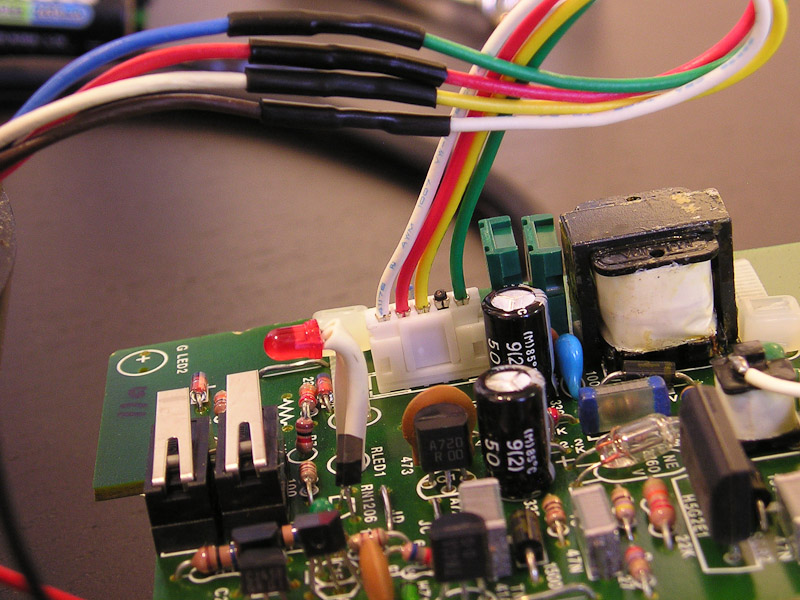
Here are my images for this modification which you can appreciate are trivial.


Important Disclaimer

This information is provided purely to document my modifications and carries no implied warranty for either correctness of content or any consequence arising from its use by anyone else.

High power strobes used dangerous high voltage electronics and 300VDC or more may be charged and ready to bite (potentially fatally) even if the strobe is turned off.
Further more, modification such as these have the potential to destroy your precious digital camera if not implemented correctly and I accept no responsibility for any event arising.

… Robert Rath 3/8/2012


References For This Article

http://www.devilgas.com/diving/ys50ttl/ys50ttl.asp
http://www.camerasunderwater.co.uk/ttl-flash-interface

Files


Virtually COMM Unicating

Sometimes it is the simplest of things that really make my day. And what is really cool is where something simple is solved in a really complex way and made to appear simple! Almost like magic in fact!!

The Problem

I have a serial device next to me connected to the comm port of my Windows PC. Let’s make it connected through a serial-usb adapter just to make things complicated. Next; I am developing an application on a remote virtual (vmware ) linux machine which needs to communicate with the small serial device next to me!

Problem 1. I have no direct access to the virtual machine in order to take my serial device and plug it into the virtual machine’s host.
Problem 2. Even if I could have my little serial device plugged into my remote virtual machine’s host I would no longer be able to interact with it during development work.

The simple solution would be to have my little serial device magically connected to my remote virtual machine and still be sitting next to me and my Windows PC.
Note my use of the word ‘simple’; simple in description but not so in solution.

The Outcome

When a problem has been nagging to the point of being insufferable it is amazing how a little action, imagination and perseverance can produce magic.
With the help of two little tools; ‘tcp2com.exe’ and ‘socat’; I am now able to enjoy the convenience of having my little serial device plugged into my Windows PC and being plugged into my remote virtual linux machine at the same time … simply magic!

The Solution

I am not going to recount chapter and verse on how I made this magic happen. I don’t want to make it easy for anyone else. So here is an incredibly terse, dot-point-list of actions I took.

Setup

On Windows
Install ‘COM2TCPInstall_1_4_0.exe’ or use ‘tcp2com-1.0.0-bin.zip’
Configure tcp2com to export comm port and settings as required.
Example, on machine 10.0.0.10 export com4,57600,n,8,1,none to port 5555

On Linux
$ sudo apt-get install socat
$ sudo socat PTY,link=/dev/remotetty0,raw,echo=0,wait-slave tcp:10.0.0.10:5555

Testing

On Windows
Open ‘hypertrm’ and connect to com4,57600,n,8,1,none

On Linux ( different console session )
$ sudo kermit -l /dev/remotetty0
C-Kermit->set flow none
C-Kermit->set carrier off
C-Kermit->set speed 57600
C-Kermit->connect

You should now be able to communicate between the two local terminals as if the machines were connected with a serial cable.

… enjoy 🙂


Virtually COMM Unicating

Sometimes it is the simplest of things that really make my day. And what is really cool is where something simple is solved in a really complex way and made to appear simple! Almost like magic in fact!!

The Problem

I have a serial device next to me connected to the comm port of my Windows PC. Let’s make it connected through a serial-usb adapter just to make things complicated. Next; I am developing an application on a remote virtual (vmware ) linux machine which needs to communicate with the small serial device next to me!

Problem 1. I have no direct access to the virtual machine in order to take my serial device and plug it into the virtual machine’s host.
Problem 2. Even if I could have my little serial device plugged into my remote virtual machine’s host I would no longer be able to interact with it during development work.

The simple solution would be to have my little serial device magically connected to my remote virtual machine and still be sitting next to me and my Windows PC.
Note my use of the word ‘simple’; simple in description but not so in solution.

The Outcome

When a problem has been nagging to the point of being insufferable it is amazing how a little action, imagination and perseverance can produce magic.
With the help of two little tools; ‘tcp2com

pm’ and ‘socat’; I am now able to enjoy the convenience of having my little serial device plugged into my Windows PC and being plugged into my remote virtual linux machine at the same time … simply magic!

The Solution

I am not going to recount chapter and verse on how I made this magic happen. I don’t want to make it easy for anyone else. So here is an incredibly terse, dot-point-list of actions I took:

On the Windows PC, install ‘COM2TCPInstall_1_4_0.exe’ or use ‘tcp2com-1.0.0-bin.zip’
Configure tcp2com to export comm port and settings as required.
* For example on machine 10.0.0.10 export com4,57600,n,8,1,none to port 5555

On Linux
$ sudo apt-get install socat
$ sudo socat PTY,link=/dev/remotetty0,raw,echo=0,wait-slave tcp:10.0.0.10:5555
$ sudo kermit -l /dev/remotetty0

… enjoy 🙂